Contents
- Introduction
- Blur Concepts
- Gaussian Blur Basics
- Outline of the Horizontal Blur Process
- General Concept of Setting up a Blur Scene
- Methods to Improve Performance
- Coding in Three JS
- Conclusion & Earth Example
Related Articles
Using WebGL in Web Design
This article provides a more in-depth look at what WebGL is, and how it can be utilized to design dynamic, visually unique websites, and goes through more examples of uses of WebGL and how it can enhance web design.
WebGL / ThreeJS Glow Tutorial Using Gaussian Blurring
By: Sean Peplinski
Date Published: 10/14/2016
INTRODUCTION
The purpose of this article is to give 3D programmers an introduction to the blurring process in 3D graphics. This article will focus on a widely-used application of blurring that requires some setup – namely, the glow effect. I will first describe the technical aspects of setting up blurring effects, and then delve into a practical application with code examples.A few other applications of blurring are: realistic reflections, image/video processing, and camera effects such as motion blur and bloom. Since blurring can come at a heavy performance cost, especially on mobile and older hardware, it is imperative that all measures are taken to make sure blurring is implemented as efficiently as possible. This article is written in reference to THREEJS / WebGL projects, but of course, the concepts can be applied to any 3D API.
GAUSSIAN BLUR BASICS
Multiple techniques exist to blur an image, but Gaussian blurring is typically understood to be the best technique in terms of looks and performance and this article will focus only on the Gaussian method. Before giving an outline of the Gaussian blur method, I want to point out that blurring is a post-processing process, meaning that we must use fragment (pixel) shaders to process an image of a scene after it has been rendered. Although it would be more convenient, we cannot simply apply a shader to a single object in a scene that we want to blur. In terms of 3D graphics, this means we must render a scene to a render target, and then pass that render target as a texture into the shaders doing the blurring.
Outline of the Gaussian blur method:
- First, it is important to know that in 3D graphics, Gaussian blur is commonly broken into two passes – horizontal and vertical blur. Later, we will look into why this is more efficient.
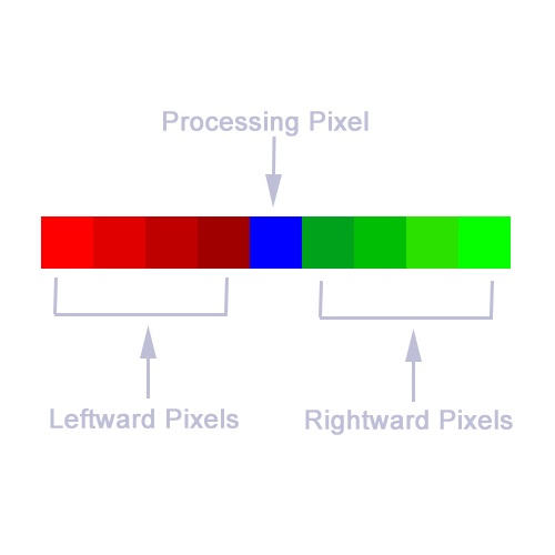
- For each pixel, sample nearby pixels (commonly 4 pixels in each direction) and take a weighted average of the color values. This means that each pixel's color will become a combination of the colors of nearby pixels.
- Pixels nearer to the pixel being processed will be given a heavier weight.
- The weights used is what makes this process “Gaussian”. Specific weights are given to nearby pixels based on a Gaussian distribution. The example below will further explain what this means in practice.
Why two blur passes?:
- As mentioned above, the Gaussian blur process is generally broken into two passes – one that blurs the image horizontally, and one that blurs the image vertically.
- The basic explanation for why this is faster, is because we need to sample less pixels. If we were to use a single pass, we would need to sample not only pixels perpendicular and parallel with the processing pixel, but the diagonals as well. A more detailed explanation can be found here: https://software.intel.com/en-us/blogs/2014/07/15/an-investigation-of-fast-real-time-gpu-based-image-blur-algorithms
OUTLINE OF THE HORIZONTAL GAUSSIAN BLUR PROCESS
1
For each pixel, grab the original color of the pixel, grab the colors of the nearest 4 pixels to the left, and the nearest 4 pixels to the right for a total of 9 pixels.
2
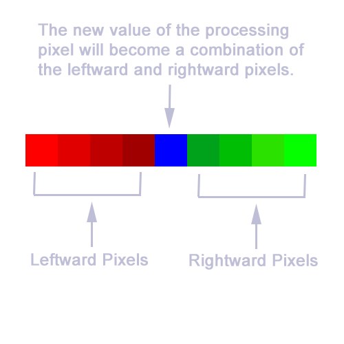
The color of the processing pixel will become a combination of the colors of the 9 pixels.
3
Mathematically, each pixel's color will be calculated as so: p = p * w0 + pl1 * w1 + pl2 * w2 + pl3 * w3 + pl4 * w4 + pr1 * w1 + pr2 * w2 + pr3 * w3 + pr4 * w4
WHERE: plx are leftward pixels, and prx are rightward pixels. w1-w4 are the weights applied to the pixels depending on how far away they are from the processing pixel. w0 is the weight of the original color of the processing pixel.
In our example, the weights are set to the following: w0 = 0.2270, w1 = 0.1945, w2 = 0.1216, w3 = 0.0540, w4 = 0.0162. It's important to examine and think about what this means. Since w1 = 0.1945, this means the nearest pixel to the right and left will each contribute 19% to the resultant color. Since w0 = 0.2270, the processing pixel will contribute 22% to the resultant color, meaning we give the most weight to the original color of the pixel we are blurring. Notice that as we go further away from the processing pixel, the weights get smaller to the point where pixels 4 units away from the processing pixel contribute only 1% to the resultant color.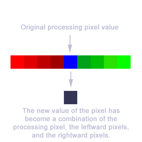
GENERAL CONCEPT OF SETTING UP A GLOW SCENE
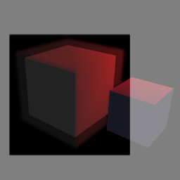
In the simplest case, a scene is rendered and passed into blur shaders where the entire scene is blurred. However, in most cases, only certain areas and objects of a scene are to be blurred. Since blurring is a post-processing process and we can't simply blur specific objects via a certain shader or material, this means that we must render a scene separate from the main scene containing only the objects that need to be blurred. After this blur scene is put through the blurring passes, the resultant image must then be overlayed on top of the regular scene after it has been rendered.The key to setting up a blur scene is to ensure that the rendered image will contain only the portion of objects that need to have blurring applied. This is not as simple as creating a scene containing only objects that need to be blurred, because the regular scene may have objects that cover up all or part of a blur object. For example, maybe we want to give a sphere a glow effect, but a cube is in front that covers up half of the sphere. Our blur scene must reflect this. Therefore, the blur scene must contain all objects of the regular scene, but non-blurring objects should effectively only create a mask over the objects that should be blurred.
So, how do we achieve this? In our blur scene, objects that should be blurred, should have the same material as the regular scene, or perhaps a slightly different material. For example, if for some reason we want a red sphere to glow blue, the object in the regular scene would have a red material, while the object in the blur scene would have a blue material. If the red sphere is supposed to glow red, the objects in the regular scene and the blur scene could be identical. Now, objects that are not to be blurred should simply have a transparent material. If we were to write a fragment shader for these objects, the main method of the shader would simply be: “gl_FragColor = vec4(0.0, 0.0, 0.0, 0.0);”. This effectively means that anywhere a non-blurred object appears in the blur scene, that area of the blur image will simply be transparent. This works out once we overlay the blur image over the rendered regular scene.
METHODS TO IMPROVE PERFORMANCE
From examining the Gaussian blur process, we see that for each pixel in the image, we need to sample 18 pixels between two blurring passes. In a fragment shader, sampling a texture via a method such as 'texture2D' is an expensive operation for a GPU processor – especially on mobile and older hardware. Notice that for an image with a resolution of 1920x1080, this means we need to sample 18 * 1920 * 1080 = 37,324,800 pixels for each frame we render. If we are targeting a frame rate of 60 FPS, this means the user's GPU must be able to make 2.2 billion samples per second in addition to the other overhead of the scene being rendered. This can be very demanding for many devices, so it's very important that we reduce the required samples if possible. For many scenes, it's often the case that not every pixel in the scene needs to be blurred. For example, perhaps much of the image is empty, except for a small sphere in the middle of the image. Unless we add some additional enhancements to the blurring process, it's possible we are wasting a great amount of processing power blurring pixels that don't need to be blurred. Below, I'll outline some methods we can use to limit the pixels that end up going through the Gaussian blur equation. Each method has performance/effectiveness trade-offs, so you need to select the method that's best for your scene.Reducing Resolution of Glow Scene
A quick and easy way to reduce the performance-cost of blur shaders is to reduce the resolution of the render target we are processing. This, of course reduces the quality of the blurred image, but for certain applications, like glowing, the quality loss can be tolerated. Later, we will examine how to reduce the resolution of render targets in THREE JS.Masking
In the next section, we will examine a few methods of how we can use masks to only apply blurring in certain areas. First, we will look at using a blur mask scene to pass in a texture to the blur shaders so that only selected areas go through the blur processing. Then, we will look at an alternate method using the stencil buffer. The stencil buffer method is cleaner, faster, and can be used in most scenarios, but it's good to have knowledge of both methods.Bounding Box
The simplest method to select which area of the image gets blurred is to implement a bounding box by defining vec2 uniform variables of: 'topRight, bottomLeft'. Then, before doing any sampling, we check that the texel we are processing is within the bounds of the box. Below, we will look at how we can give our glow objects bounding boxes and compute a single screen bounding box that will be passed into the blur shaders that defines which portion of the image gets blurred.Skip Pixels With No Color
This method is simply to skip blurring for pixels that have no color (eg. vec4(0.0, 0.0, 0.0, 0.0). This is a very simple and effective method to skip blurring on unneeded pixels, but the trade-off is that the blurring will only occur in the internal portion of objects. Edges will remain hard, making this an invalid masking method for glow effects. Note that when using this method, only 2 samples need to be taken for pixels that don't need blurring (one sample in the horizontal pass, and one sample in the vertical pass).SETTING UP A SIMPLE BLUR EFFECT IN THREEJS
Now, let's get into some code and practical examples of using blur. We'll start off simple and gradually add more features to our scene. Ultimately, we'll work up to achieve the best blur effect with the most optimization.BLURRING A CUBE

JSFiddle: https://jsfiddle.net/SeanPeplinski/2fczyr0g/
If you're familiar with THREE JS, the code in the fiddle example is quite self explanatory. We are creating a simple scene with one cube and a few lights. A THREE.EffectComposer is then used to render the scene and subsequent blurring passes. Please note that the fragment/vertex shaders are included in the HTML under “script” tags. Let's examine the main method of the horizontal blur fragment shaders (of course, the concepts are similar for the vertical blur shader):
void main() {
    vec4 sum = vec4(0.0);

    vec4 originalSample = texture2D(tDiffuse, vUv);

    sum += texture2D(tDiffuse, vec2(vUv.x - 4.0 * h, vUv.y)) * 0.0162;
    sum += texture2D(tDiffuse, vec2(vUv.x - 3.0 * h, vUv.y)) * 0.0540;
    sum += texture2D(tDiffuse, vec2(vUv.x - 2.0 * h, vUv.y)) * 0.1216;
    sum += texture2D(tDiffuse, vec2(vUv.x - 1.0 * h, vUv.y)) * 0.1945;
    sum += originalSample * 0.2270;
    sum += texture2D(tDiffuse, vec2(vUv.x + 1.0 * h, vUv.y)) * 0.1945;
    sum += texture2D(tDiffuse, vec2(vUv.x + 2.0 * h, vUv.y)) * 0.1216;
    sum += texture2D(tDiffuse, vec2(vUv.x + 3.0 * h, vUv.y)) * 0.0540;
    sum += texture2D(tDiffuse, vec2(vUv.x + 4.0 * h, vUv.y)) * 0.0162;

    gl_FragColor = sum;
}Samplers use normalized coordinates between 0.0 and 1.0. Meaning if an image size is 500x500 pixels, a sample of the middle of the image would use the coordinates (0.5, 0.5) instead of something like (250, 250). So, in the shader above, when we use coordinates like (vUv.x + n * h, vUv.y), we are effectively sampling 'n' texels away from the current texel we are processing. Notice that since coordinates can be any number between 0.0 and 1.0, we may not be sampling a texel corresponding exactly to one pixel of the image. Bilinear interpolation is used when sampling between pixels. This means that if we happen to sample a texel exactly in the middle of two pixels, we get an average of the two pixels. For example, let's say the coordinates of two pixels are (0.45, 0.45) and (0.46, 0.45). If we sample (0.455, 0.45), we'll get an average of the two pixels. If we sample (0.4525, 0.45), we'll get a color that is 75% the color of the pixel at (0.45, 0.45), and 25% the color of the pixel at (0.46, 0.45). This fact will come in handy when we optimize the blur process.
CREATING A GLOW SCENE
JSFiddle: https://jsfiddle.net/SeanPeplinski/007hve12/
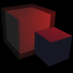
Now, let's go a little further by creating a glow effect for the cube, as well as adding a non-glowing cube in front of the glowing cube. You'll notice in the code that there are now two scenes – “scene” and “blurScene” as well as a composer for each scene. There is also a new fragment shader called “overlayFrag”.
First, let's talk about the two scenes. The “scene” object contains both the cube that will eminate a glow, and the non-glowing cube. The “blurScene” object contains one cube that represents the glow – notice it is slightly bigger than the cube in the regular scene, thus giving a glow effect. The “blurComposer” will render the glow scene and apply a blur to the rendered output. The “sceneComposer” will simply render the regular scene and overlay the output of the “blurComposer”. So that we can successfully use the alpha channel of the “blurComposer” output, it's important that we set both the read/write render targets to the format of RGBA (as opposed to the default value of RGB):
blurComposer.renderTarget2.texture.format = blurComposer.renderTarget1.texture.format = THREE.RGBAFormat;void main() {
vec4 regularScene = texture2D(tDiffuse, vUv);
vec4 overlay = texture2D(tOverlay, vUv);
float blurOpacity = 0.5;
overlay.a *= blurOpacity;
gl_FragColor = vec4(regularScene.rgb * (1.0 - overlay.a) + overlay.rgb * overlay.a, 1.0);
}OPTIMIZATION
Now, let's focus on how we can improve the speed of the blur passes. This is especially important for older hardware and mobile devices. First, we will see how we can reduce the number of samples for each texel we process, and then, how we can reduce the area we actually execute blurring on.REDUCING BLUR RENDER TARGET RESOLUTION
By reducing the resolution of the render target that our blur shaders operate on, we can reduce the amount of samples needed for each frame. If we reduce the resolution by ½, we also reduce the number of required samples by ½. Of course, this also reduces the quality of the blurred image, but this can be tolerated for some applications of blurring, like glow effects. THREE JS makes reducing the render target resolution very easy. In THREE JS, we can simply set the resolution of a composer object which in turn, sets the resolution of the render targets used by all passes belonging to that composer. For our example, the code below sets the resolution of our blur composer. Note that this is not setting the resolution of the entire scene, but only of the blur image that we will overlay on top of the rendered image of the scene.blurComposer.setSize(window.innerWidth / 2, window.innerHeight / 2);REDUCING THE NUMBER OF NEEDED SAMPLES
JSFiddle: https://jsfiddle.net/SeanPeplinski/97zo3xsh/Using the bilinear property of texture access mentioned in the “Blurring a Cube” section, we can reduce the number of samples required by half. Remember, by sampling a texture in between two texels, we can get a weighted average of the two texels. By sampling exactly in the middle of two texels, we get an average of the two texels. By sampling closer to either pixel, we can get any mix of the two texels that we want. This comes in very handy for blurring, because instead of sampling two texels – each with their own weight, we can sample a texel in between with a new weight that effectively gives us the same result. We can calculate the new weights and offsets using the following formulas:
NewWeight = weight(texel1) + weight(texel2)
NewOffset = (offset(texel1) * weight(texel1) + offset(texel2) * weight(texel2)) / NewWeight
Our new shader is now:
void main() {
    vec4 sum = vec4(0.0);
    vec4 originalSample = texture2D(tDiffuse, vUv);

    sum += texture2D(tDiffuse, vec2(vUv.x - 3.2307 * h, vUv.y)) * 0.0702;
    sum += texture2D(tDiffuse, vec2(vUv.x - 1.3846 * h, vUv.y)) * 0.3162;
    sum += originalSample * 0.2270;
    sum += texture2D(tDiffuse, vec2(vUv.x + 1.3846 * h, vUv.y)) * 0.3162;
    sum += texture2D(tDiffuse, vec2(vUv.x + 3.2307 * h, vUv.y)) * 0.0702;

    gl_FragColor = sum;
}void main() {
vec4 sum = vec4(0.0);
vec4 originalSample = texture2D(tDiffuse, vUv);
sum += texture2D(tDiffuse, vec2(vUv.x - 3.5 * h, vUv.y)) * 0.0702;
sum += texture2D(tDiffuse, vec2(vUv.x - 1.5 * h, vUv.y)) * 0.3162;
sum += originalSample * 0.2270;
sum += texture2D(tDiffuse, vec2(vUv.x + 1.5 * h, vUv.y)) * 0.3162;
sum += texture2D(tDiffuse, vec2(vUv.x + 3.5 * h, vUv.y)) * 0.0702;
gl_FragColor = sum;
}CREATING A BLUR MASK SCENE
JSFiddle: https://jsfiddle.net/SeanPeplinski/6j8mwhg5//We can limit the area of the blur scene we execute blurring on by creating a mask scene and composer. The mask will allow us to skip the blurring process for texels that are not within the mask. For example, in our scene, the glow cube only takes up a small section of the scene, but we are blurring the entire image which is mostly transparent (seen as black in our scene). This is a lot of wasted processing power that is needlessly reducing the frame rate of the scene.
The main changes to accommodate the blur mask are in the “SetupComposers” function. The “blurMaskComposer” will render our new scene called “blurMaskScene”. This scene only contains a cube that is slightly larger than the glow cube. The new object is slightly larger so that we are sure to include blurring on the entire object as well as its edges. Experiment with the size of the “glowCubeMask” object to see how this effects the output. If you reduce the size, you'll notice that the glow cube starts to get cut off because it is no longer entirely within the mask.
Also notice that a “mask” parameter has been added to the “CreateBlurShaderPasses” so that each blur pass created has a reference to the render target of the “blurMaskComposer”. The blur mask will be represented in the shader as a texture called “tMask”. Here are the changes to the blur fragment shaders:
// Only blur the area where the mask is white.
if(texture2D(tMask, vUv) != vec4(1.0)) {
    gl_FragColor = vec4(0.0);
    return;
}The downside of using a blur mask is that we have an additional scene to render. However, in some cases, the performance gained by only blurring targeted areas can outweigh the performance cost of rendering the blur mask scene. Whether to use a blur mask is something you will need to decide based on the specifics and complexity of your scene. If, for example, you require a large portion of the rendered scene image to be blurred, a blur mask will add little benefit, and may possibly even decrease your frame rate.
USING THE STENCIL BUFFER
JSFiddle: https://jsfiddle.net/SeanPeplinski/2k0ob1um/Using the stencil buffer is similar in concept to the blur mask scene method above, but the code is cleaner and we do get a performance bump over the mask scene method. Before continuing, feel free to read over this article if you need more information about the stencil buffer: https://open.gl/depthstencils
THREE JS makes the utilization of the stencil buffer very convenient. All we need to do is make sure the render target of the blur composer contains a stencil buffer, and then add two passes to the composer – one to write to the stencil buffer, and one to clear the stencil buffer so that it does not interfere with the drawing of the regular scene.
var renderTargetParameters = { minFilter: THREE.LinearFilter, magFilter: THREE.LinearFilter, format: THREE.RGBAFormat, stencilBufer: true };
var blurRenderTarget = new THREE.WebGLRenderTarget(window.innerWidth, window.innerHeight, renderTargetParameters );
var maskPass = new THREE.MaskPass(blurMaskScene, camera);
var clearMaskPass = new THREE.ClearMaskPass();
blurComposer.addPass(blurPass);
blurComposer.addPass(maskPass);
blurComposer.addPass(blur1Passes.horizontalPass);
blurComposer.addPass(blur1Passes.verticalPass);
blurComposer.addPass(blur2Passes.horizontalPass);
blurComposer.addPass(blur2Passes.verticalPass);
blurComposer.addPass(clearMaskPass);BOUNDING BOX
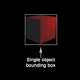
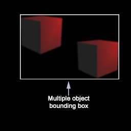
JSFiddle: https://jsfiddle.net/SeanPeplinski/c2c2r0za/This is a less accurate, but faster way to reduce sampling. Rather than rendering a new scene and using it as a mask, we will define bounding boxes for our glow objects and calculate the screen coordinates of them depending on the object and camera position. Although we will have to spend some processing power on these calculations, it will be much faster than rendering a mask scene. The downside is that we can only use one bounding box in our fragment shaders before the performance cost is not beneficial. So, the basic process is to define vertices for the bounding boxes of our glowing objects (the glowing object in our scene is simply a cube, but we can create bounding boxes for objects of any complexity), then transform the vertices of the bounding boxes based on object and camera transformations. Lastly, we examine all the vertices of the bounding boxes to create one bounding box in screen coordinates based on the vertically highest/lowest vertices, and horizontally leftmost/rightmost vertices. This method works great if our blur objects appear close to each other in screen space, however, a blur mask scene is a better choice of the blur objects are scattered across the entire screen. For simplicity, our example only includes one glowing object and thus one bounding box, but the concept can be extended to multiple objects.
At the top of our javascript file are two new object definitions called “ScreenBoundingBox” and “BoundingBoxVertices”. The purpose of “BoundingBoxVertices” is to store the vertices of the bounding box for our glow cube and to compute the “ScreenBoundingBox” object that will be passed into our blur shaders. Now, let's take a look at the javascript and fragment shader changes.
BoundingBoxVertices Constructor
THREEJS provides us with a convenient method to define vertices of a cube with specific dimensions. We can instantiate an object of type THREE.CubeGeometry to represent the bounding box and use its “vertices” array for processing in the “UpdateScreenBoundingBox” method.
var boundingBoxGeometry = new THREE.CubeGeometry(width, height, depth);This method takes in a “ScreenBoundingBox” object as a parameter, and will populate the values based on the left/rightmost and bottom/topmost vertices of the bounding box after being transformed into screen coordinates. First, we reset the “ScreenBoundingBox” object to values that would encompass the entire screen. We will then update the values as we process the transformed bounding box vertices.
screenBoundingBox.TopRight.x = 0; screenBoundingBox.TopRight.y = 0;
screenBoundingBox.BottomLeft.x = 1; screenBoundingBox.BottomLeft.y = 1;var transformedVertex = new THREE.Vector3()
.copy(boundingBoxGeometry.vertices[i])
.applyMatrix4(matrixWorld)
.project(camera);transformedVertex.x = (transformedVertex.x * 0.5) + 0.5;
transformedVertex.y = 1.0 - ((transformedVertex.y * -0.5) + 0.5);if(transformedVertex.x < screenBoundingBox.BottomLeft.x) screenBoundingBox.BottomLeft.x = transformedVertex.x;
if(transformedVertex.y < screenBoundingBox.BottomLeft.y) screenBoundingBox.BottomLeft.y = transformedVertex.y;
if(transformedVertex.x > screenBoundingBox.TopRight.x) screenBoundingBox.TopRight.x = transformedVertex.x;
if(transformedVertex.y > screenBoundingBox.TopRight.y) screenBoundingBox.TopRight.y = transformedVertex.y;The CreateBlurShaders method has been modified to use the “ScreenBoundingBox” object as a uniform value that will be used in the blur fragment shaders.
HBlur.material.uniforms.screenBoundingBox.value = screenBoundingBox;
VBlur.material.uniforms.screenBoundingBox.value = screenBoundingBox;In our render loop, we are updating the world matrix of the glow cube to make sure any transformations are included in its “matrixWorld” field. Then, we are making the call to “UpdateScreenBoundingBox”. The changes to the “screenBoundingBox” object made by “UpdateScreenBoundingBox” will be reflected in the blur shader uniforms because of the code displayed above in “CreateBlurShaders”.
glowCube.updateMatrixWorld();
glowCubeBoundingBoxVertices.UpdateScreenBoundingBox(glowCube.matrixWorld, camera, screenBoundingBox);First, we have created a structure that corresponds to the “ScreenBoundingBox” object in our javascript file and created a uniform of that type.
struct ScreenBoundingBox
{
    vec2 TopRight;
    vec2 BottomLeft;
};
uniform ScreenBoundingBox screenBoundingBox;if(!all(greaterThan(vUv, screenBoundingBox.BottomLeft)) || !all(lessThan(vUv, screenBoundingBox.TopRight))) {
gl_FragColor = vec4(0.0, 0.0, 0.0, 0.0);
return;
}
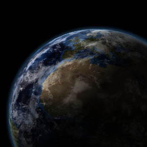
CONCLUSION
The purpose of this article was to give an overview of how to implement blurring in WebGL using the Three JS library. Further, the article outlined many ways to optimize the blur process since it is a relatively performance intensive task. I wanted to demonstrate these concepts with a very simple scene with no extraneous complications. The consequence of this is a visually underwhelming scene for the sake of simplicity. To see a more interesting example with these same concepts applied, feel free to take a look at the WebGL Earth example below. This is a very simple example that doesn't require a separate tutorial. Instead of cubes, our objects in the scene are spheres. To keep the scene optimized as much as possible, I'm only drawing one Earth object, and sampling two wrapped textures - one for the Earth, and one for the clouds. Since the textures are seamlessly wrapped, we can increment the 'u' coordinate infinitely for both textures giving a rotation effect. The 'u' coordinate for the cloud texture is incremented slightly faster to give the illusion of a separate layer above the Earth. The textures used in this scene were grabbed from this website: http://www.blenderguru.com/tutorials/create-a-realistic-earth/.WebGL Earth example using the concepts of this tutorial: